Science begins in curiosity; art begins in silence.
Where physics, art, and inner practice meet.
Program Manager, Applied Water Physics, at Wetsus – Exploring water, fields, sound, and structure across science, art, and martial arts.

Where physics, art, and inner practice meet.
Program Manager, Applied Water Physics, at Wetsus – Exploring water, fields, sound, and structure across science, art, and martial arts.

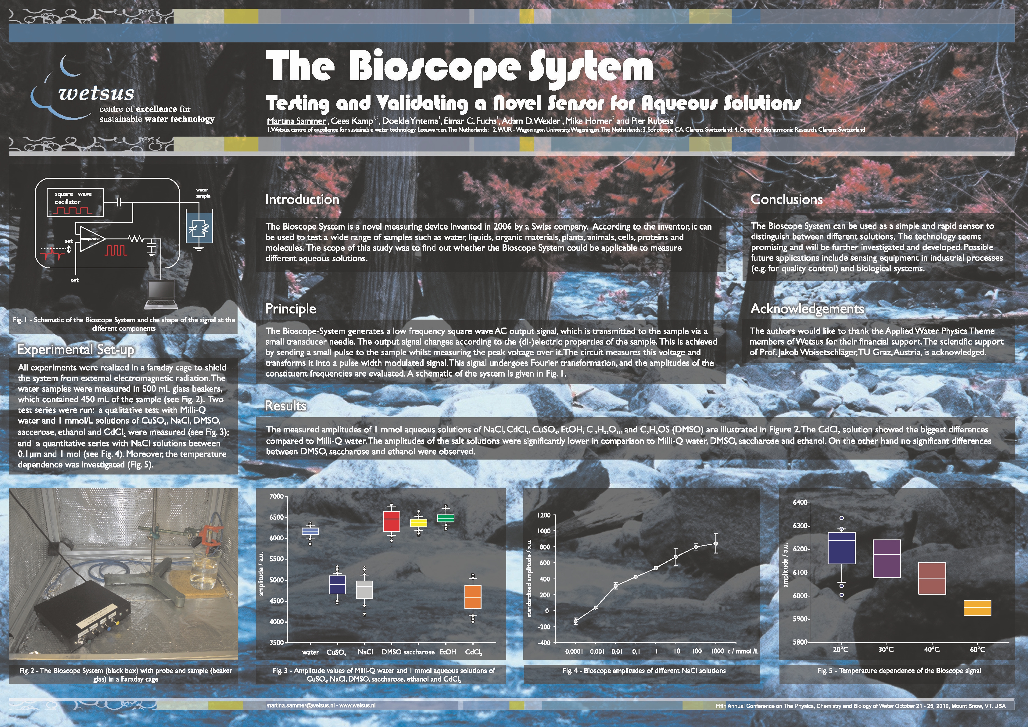
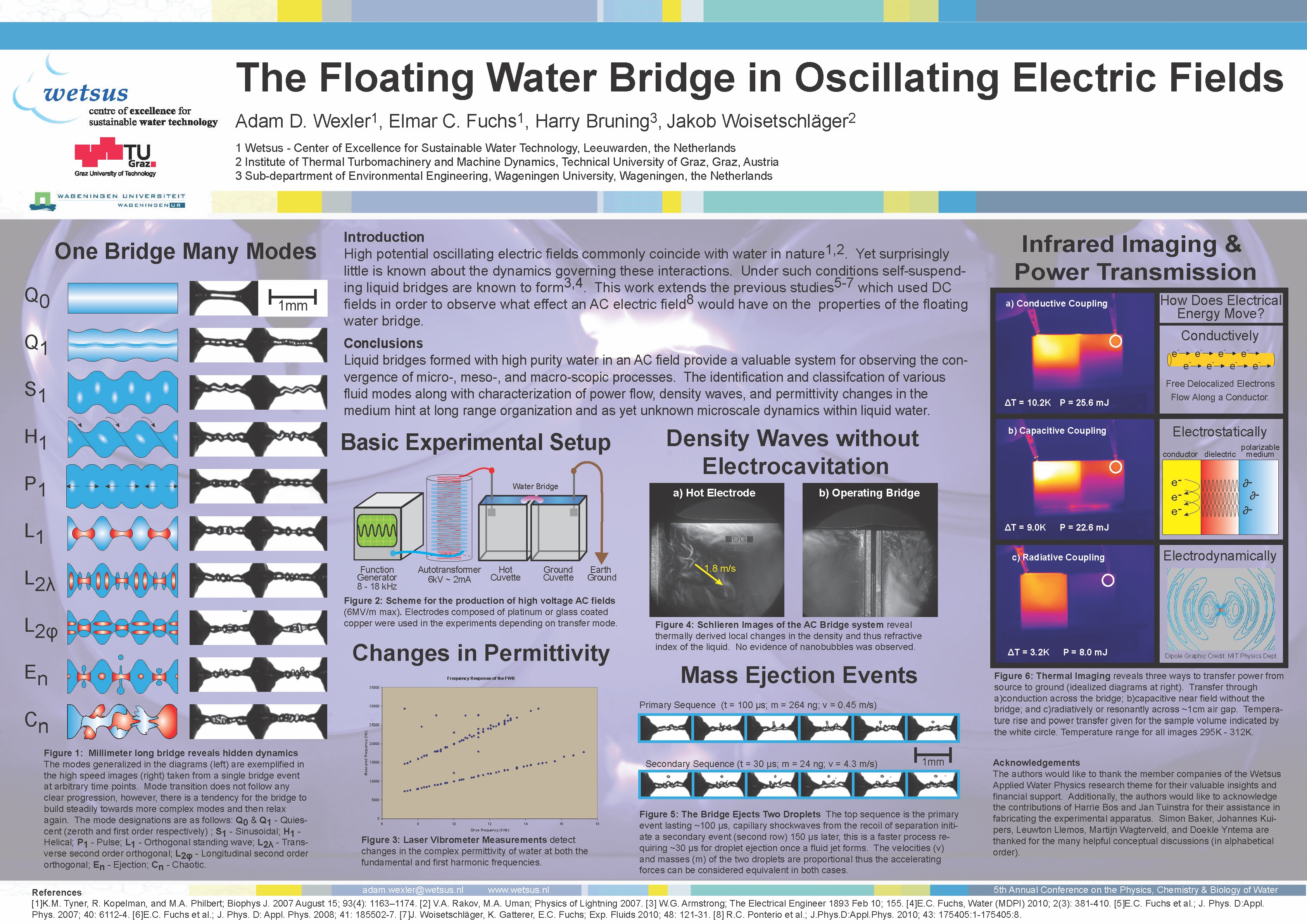
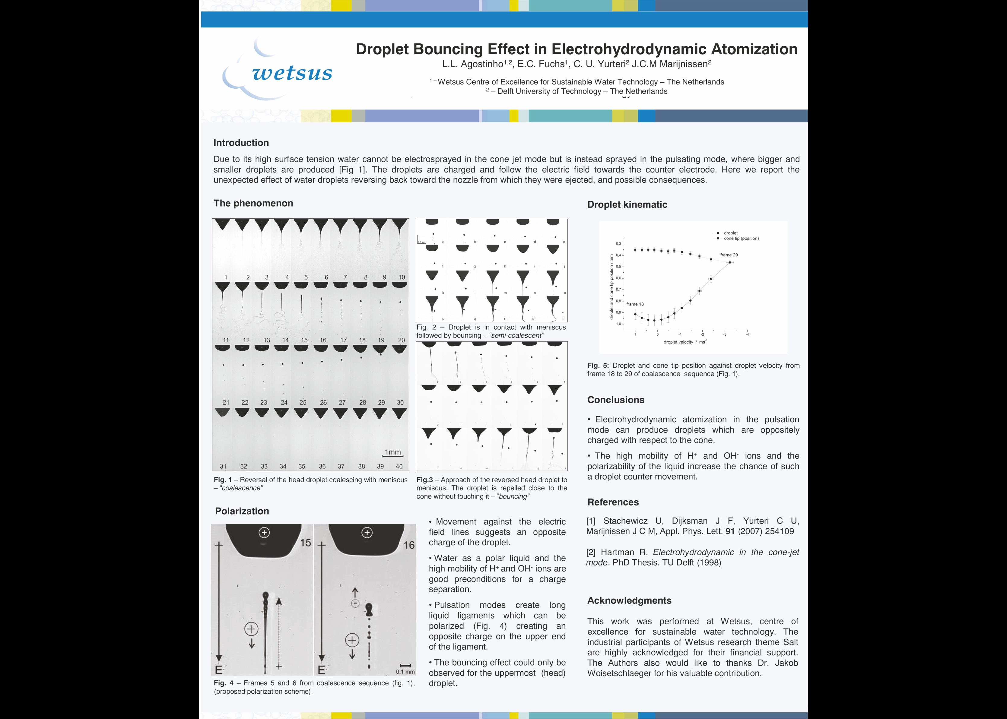
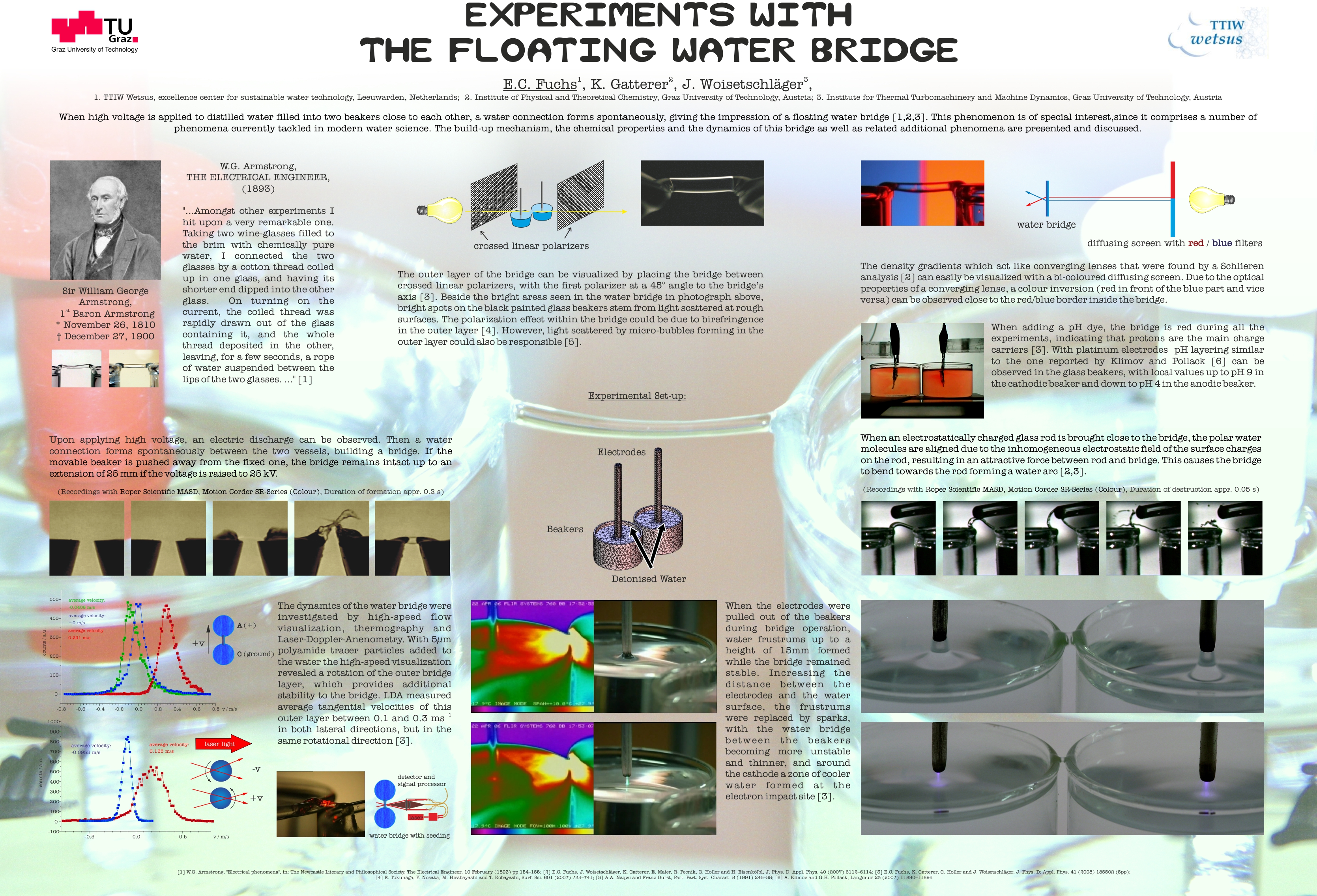
Water & physical fields
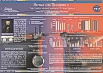
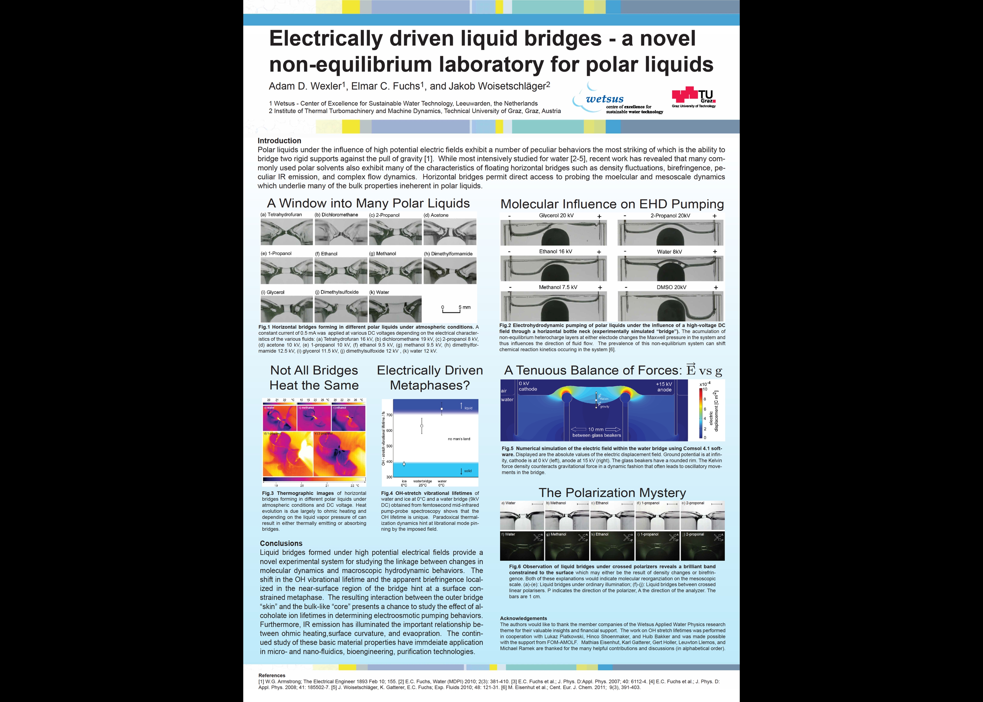
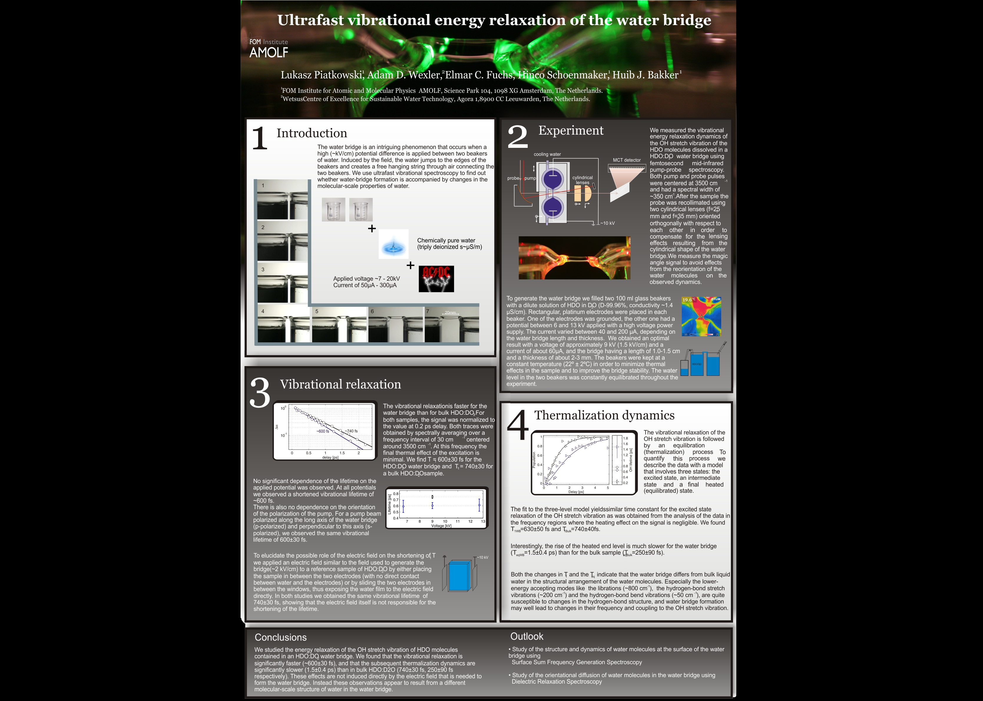
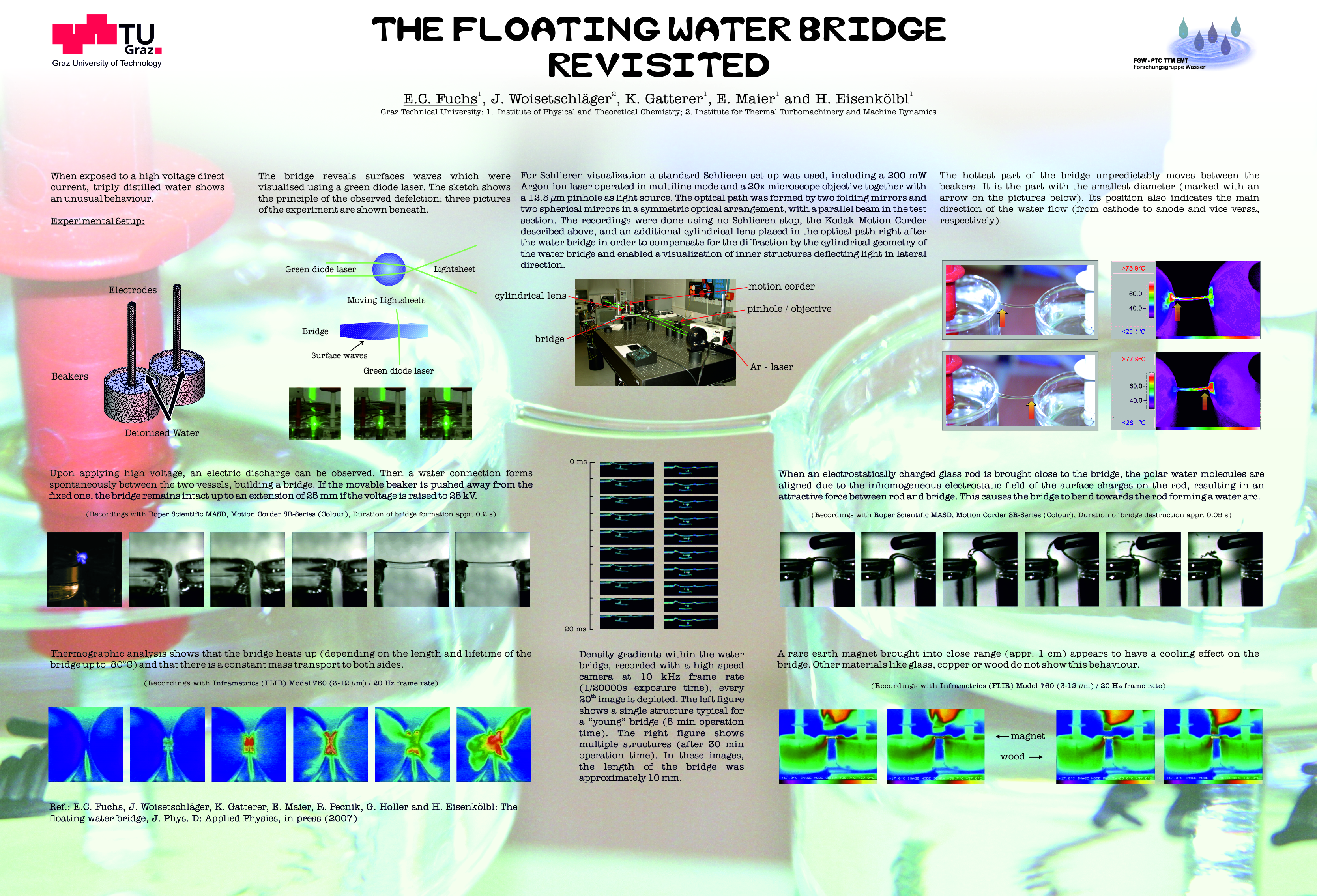
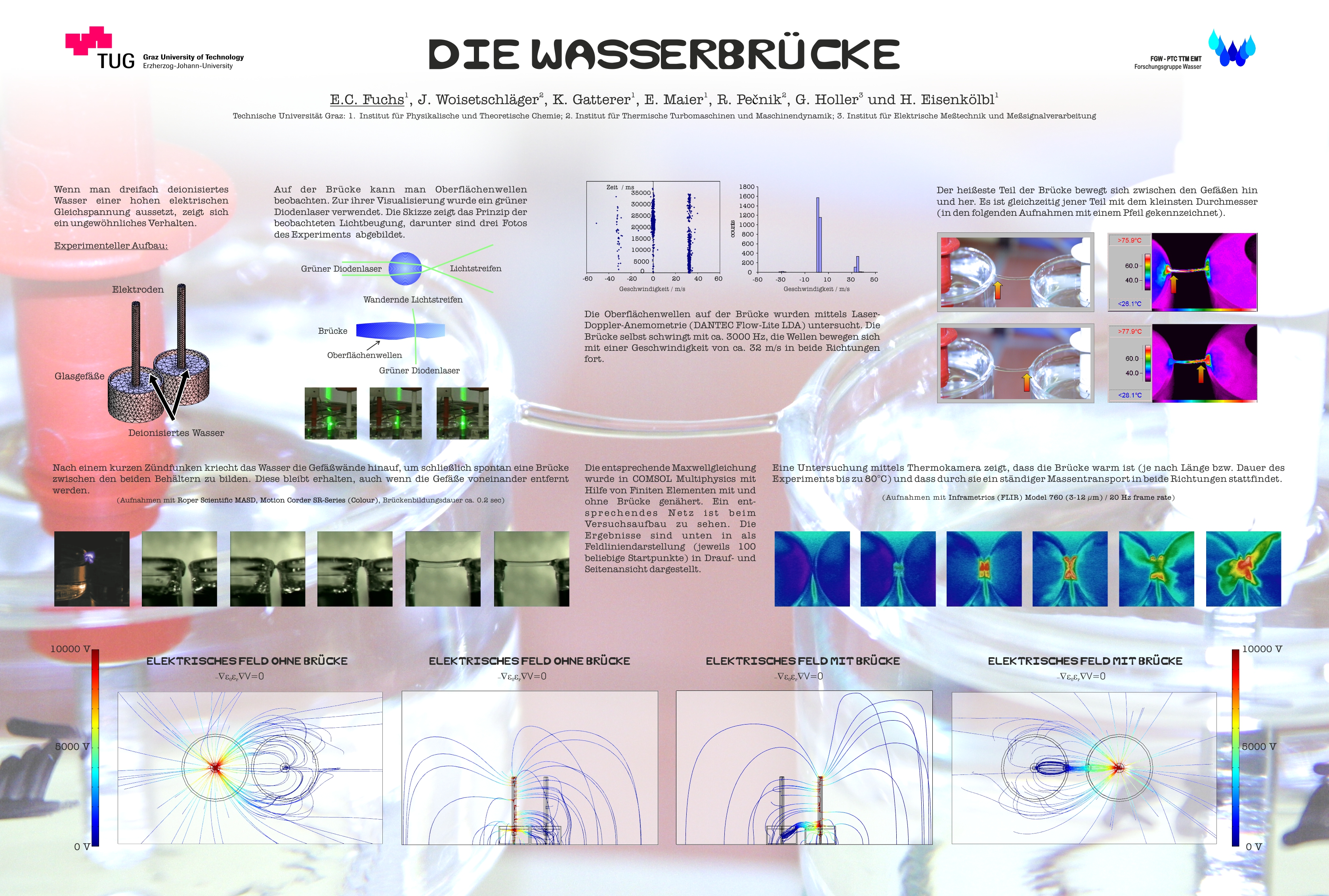
Water appears simple, yet it is one of the most extraordinary and least understood substances. Behind the modest formula H₂O lies a complex world of cooperative hydrogen bonding, quantum nuclear effects, and more than eighty documented anomalies.
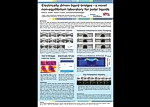
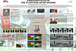
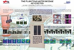
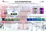
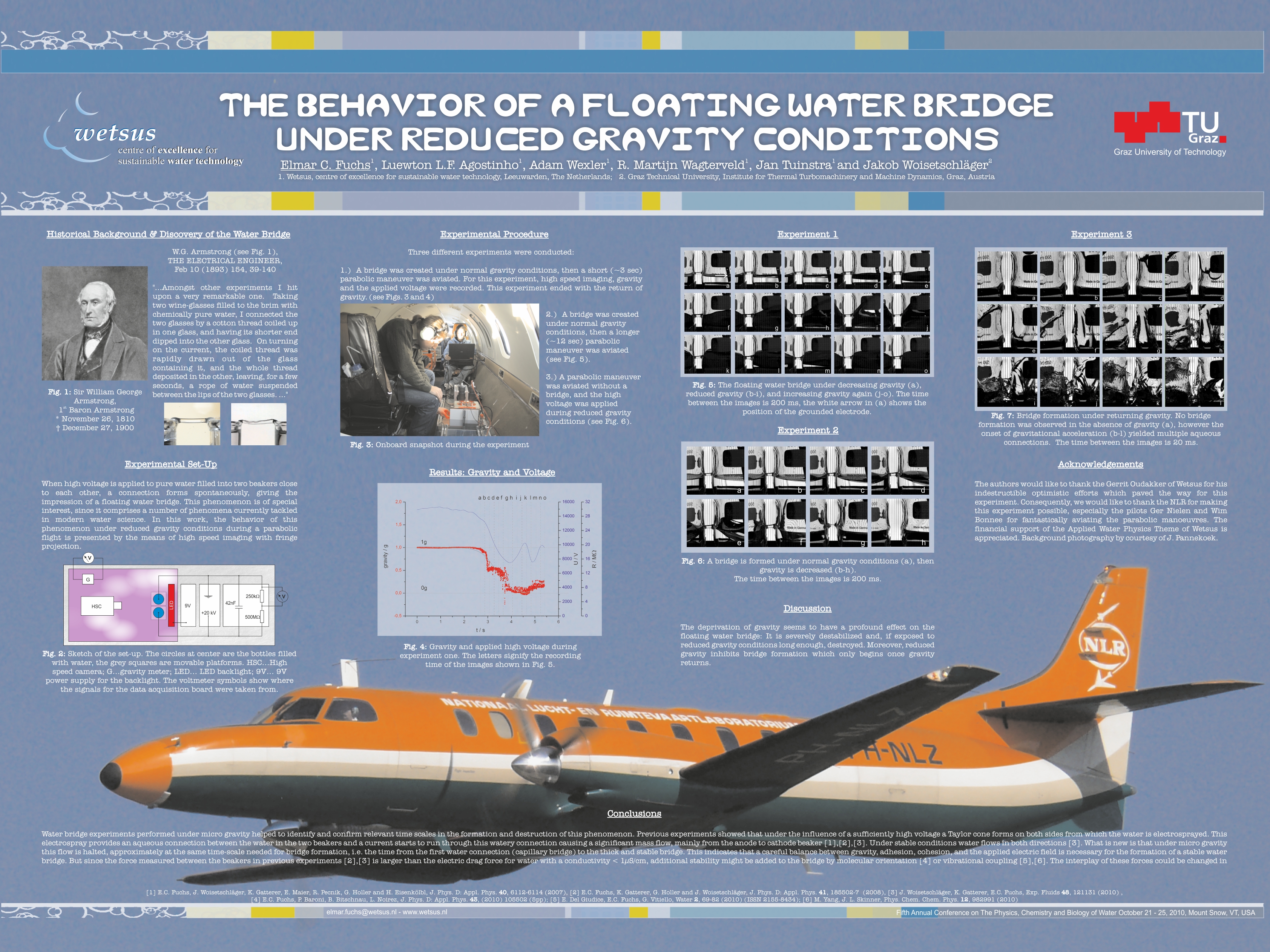
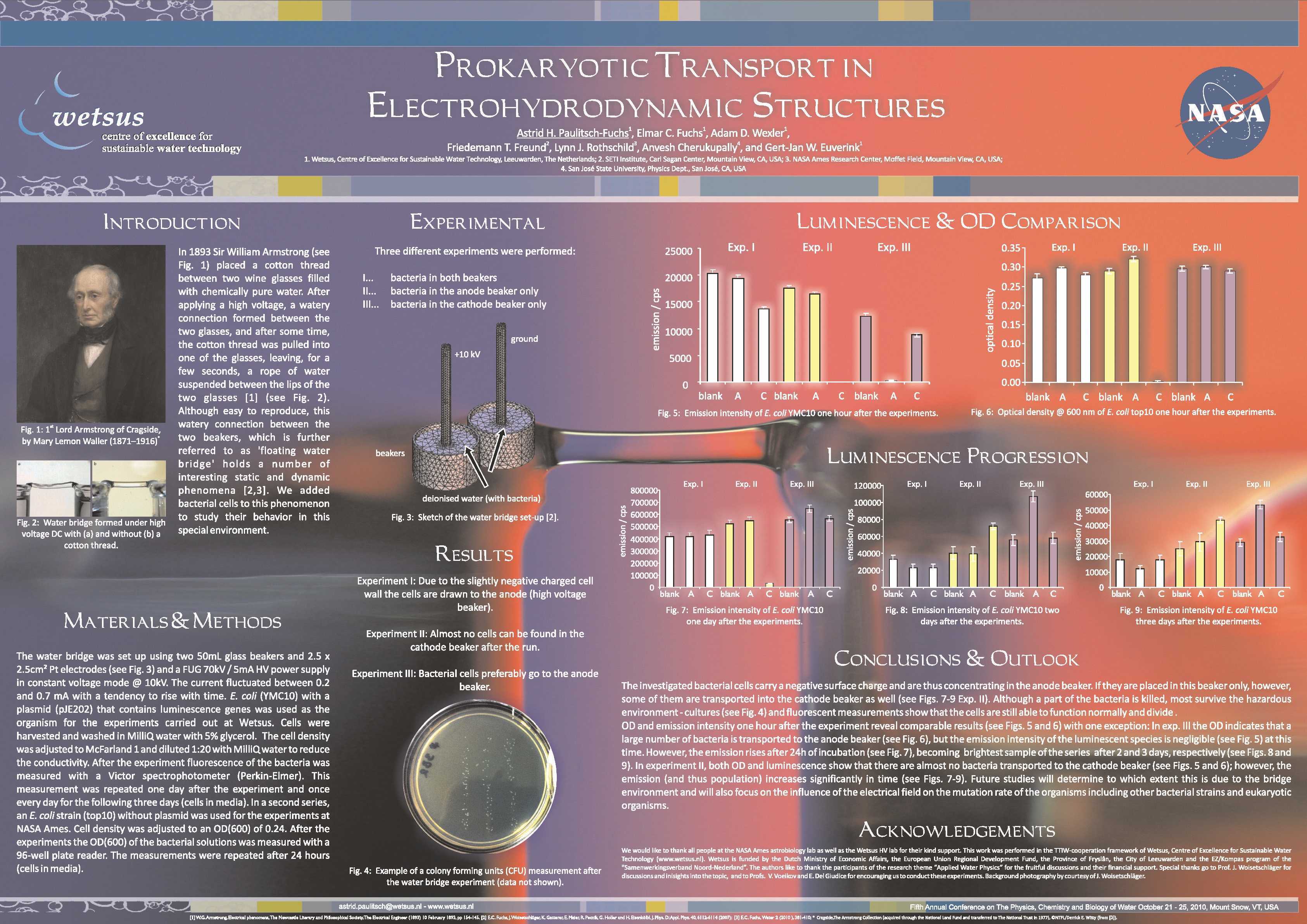
Current workfocuses on how water behaves under electric, magnetic, and electromagnetic fields – from the floating water bridge and nanobubbles to hyperbolic vortex plasma reactors. These investigations are anchored in the Applied Water Physics theme at Wetsus, and informed by studies in physics and chemistry (Dipl.-Ing., Dr. techn., TU Graz) and academic work as a non-tenured Associate Professor of Physical Chemistry (Priv.-Doz.) at the University of Vienna.
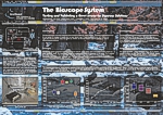
Water physics doesn't stop at the boundaries of the laboratory. Many of its unresolved questions touch on deeper principles of structure, coherence, and field interactions that extend into the cosmic scale. The Cosmic Water Foundation explores this frontier by investigating how water responds to larger natural forces — from cosmic radiation during solar eclipses to muon variations. Building upon interdisciplinary approaches, including extended quantum field theories and higher-dimensional models inspired by Burkhard Heim, the Foundation treats water not only as a chemical substance but as a sensitive, dynamic medium whose anomalous behavior may reveal new insights into fundamental physical interactions. It is a systematic, rigorous, and open exploration of phenomena at the edge of our scientific understanding.

Emotional cartography and the magic of the moment.
ELOAĦ began in 1995 as an intimate songwriting project and grew into a collaborative, genre-defying collaboration of musicians. Acoustic storytelling, rock energy, jazz spontaneity, classical nuance, and experimental textures all serve one purpose: expressing emotional truth rather than following stylistic boundaries.
Srečno is a piano–viola improvisation duo dedicated to presence. Each piece emerges spontaneously, shaped by attentive listening and the atmosphere of the moment. Silence becomes an active partner; the music exists only once, formed in real time.
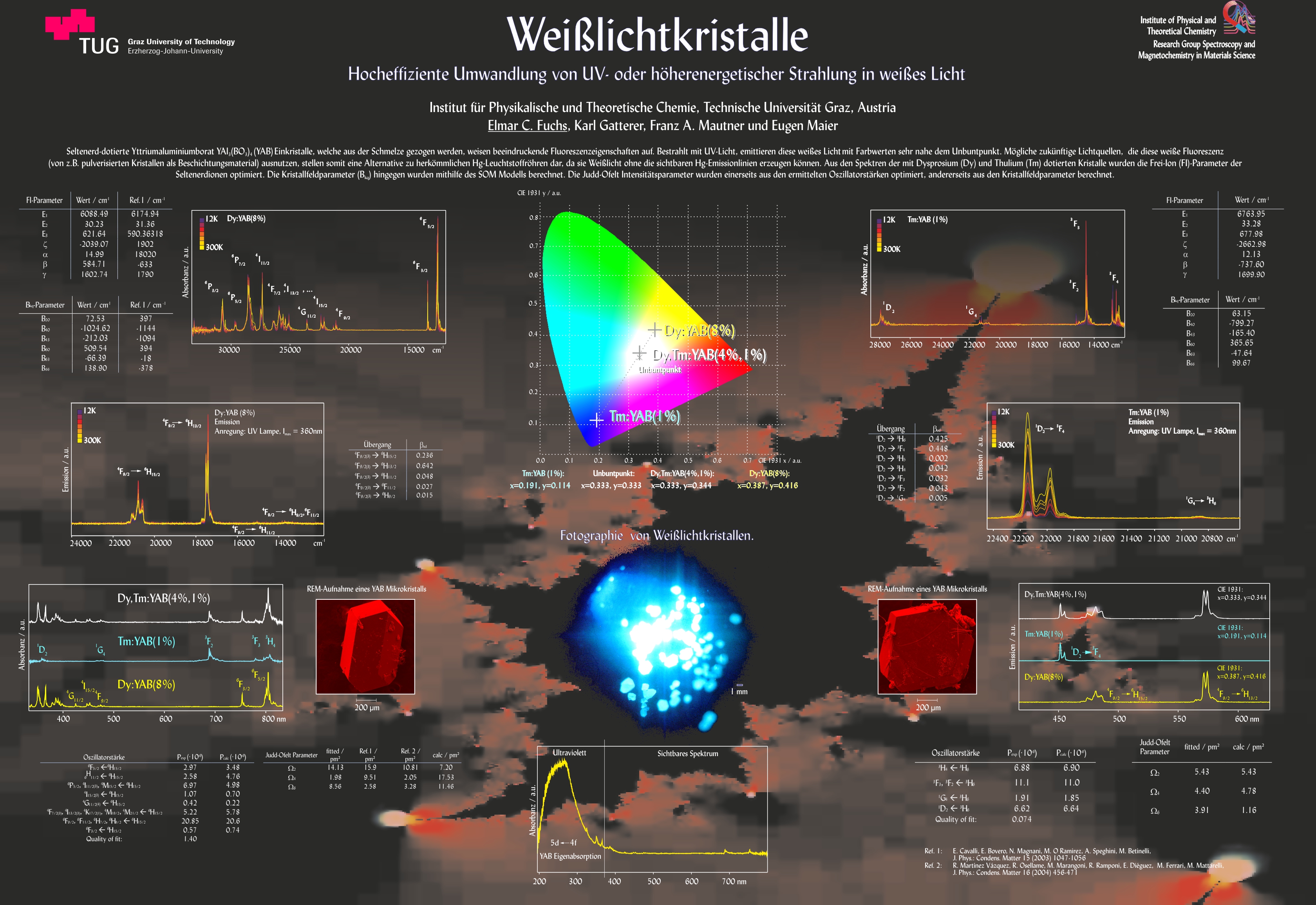
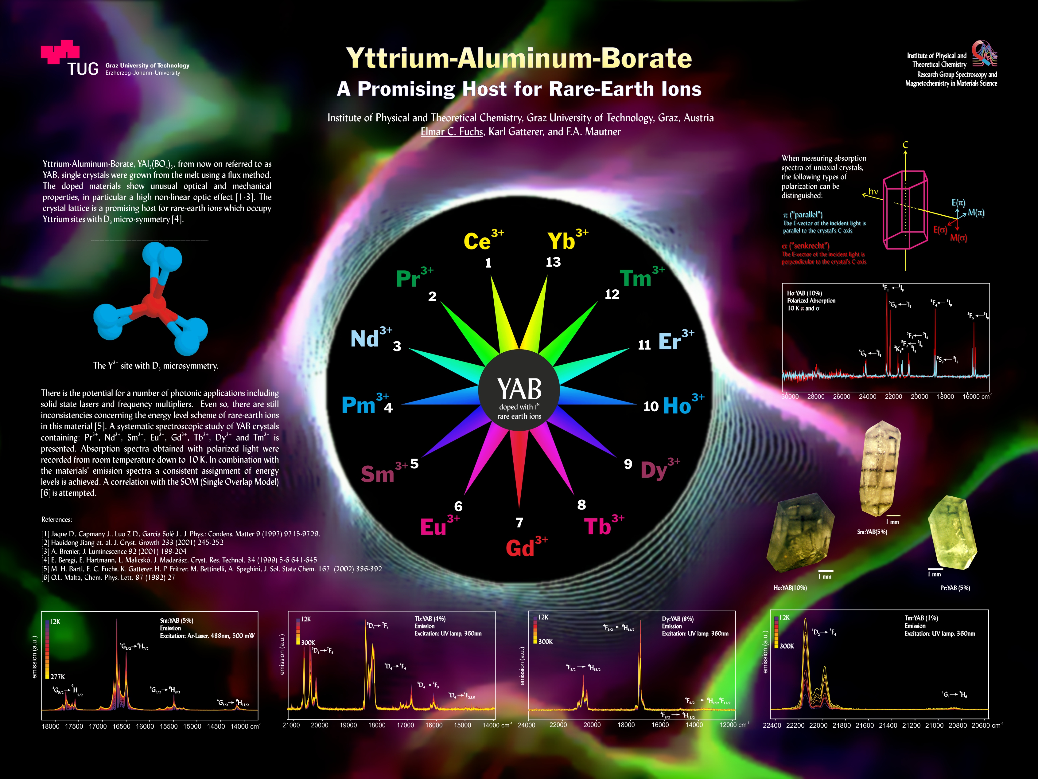
The Cosmic Water Foundation also embraces water as a cultural and aesthetic force. Its mission includes art as an essential dimension, recognizing that some aspects of water’s mystery are revealed through perception and creative expression. Scientific observation and artistic insight enrich one another. Here, water is not only studied, it is experienced and interpreted visually - and musically.

Discipline and presence.
For more than three decades, martial arts have formed a steady axis in life. Training in Kenjutsu, Tameshi Giri, Iaido, Jodo, Kendo, and Tai Chi Chuan is not approached as sport, but as a way of cultivating presence, clarity, and character. In this sense, Budō is less about technique than about understanding oneself.
Budō, the “Way” of the warrior, is rooted in the ethical tradition of Bushidō, shaped over centuries of samurai culture. Its virtues, respect, courage, sincerity, loyalty, integrity, honor, and compassion remain guiding principles today. They offer orientation in a world often driven by short-term goals, strengthening resilience and inner clarity.Through this relationship of place, people, and practice, martial arts become a lifelong discipline of humility, clarity, and inner refinement.
Holism, service, and the coherence of seemingly distant worlds.
Water serves as a guide to holism: a substance whose properties arise from interaction rather than isolated parts. Work on quantum field theory and Burkhard Heim’s unified framework reflects a commitment to exploring reality beyond conventional boundaries.
Composed music and improvisation function as parallel investigations into structure and emotion, where sound becomes a map of inner landscapes and a dialogue with silence.
A commitment to responsibility and cultural continuity is reflected in the investiture as a Knight of the Order of St. George, a European order of the Habsburg-Lorraine tradition, carried as a reminder of service and humility.
Across science, art, martial practice, and theory, meaning arises through relationship, and coherence becomes visible when boundaries dissolve. Understanding grows where curiosity is unafraid and the world is approached with both precision and wonder.
Peer-reviewed articles, selected posters, talks, patents and theses.
Required legal information according to Austrian & EU law.